Output toroids
Output toroids
Application
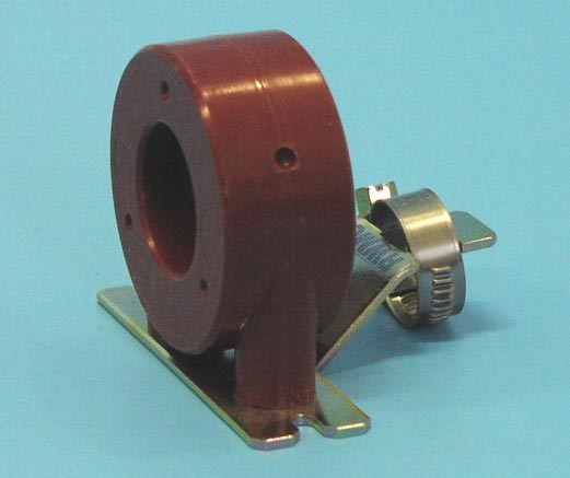
Output toroids are designed to be used at the output of a frequency converter to suppress interference (particularly in the band of 1 to 5MHz) and to limit the high-frequency capacity currents flowing between the phase conductors and the shielding of a motor cable. The toroid is equipped with a metal socket for the perfect connection of the motor cable shielding and therefore the toroid must be fixed as close to the output terminals of the frequency converter as possible by using two M4 screws on a metal base, which is common for both the frequency converter and the interference suppressor filter.
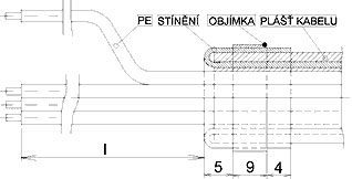
On the toroid, 2.5 turns of all phase conductors are to be wound in parallel (the PE guard conductor must be led outside the toroid) and the shielding is to be connected under the socket (Fig. 4). The maximum cross-section and recommended length of conductors for the individual toroid sizes are shown in the table. It is necessary to add to the length of conductors ("d") the distance between the toroid and the frequency converter terminals ("c"), and the sum total is the length "l" (l=d+c) as shown in Fig.4.